If you’ve ever worked with compact electronic devices—think wearables, smartphone internal assemblies, portable medical monitors, or aerospace sensor modules—you’ve likely encountered 1.00mm pitch connectors. These tiny, pin-sized connectors are the unsung heroes of modern miniaturized electronics, but one question I get asked more than any other as a supplier is a simple one: What is the impedance of a 1.00mm pitch connector? It sounds like a straightforward question, but the answer isn’t a single number—and that’s where many designers run into trouble. 1.00mm Pitch
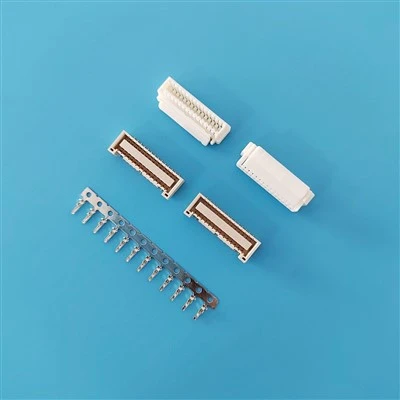
I’ve been supplying 1.00mm pitch connectors for over 12 years, and I’ve lost count of how many engineers come to me with a standard impedance target, like 50Ω or 85Ω, only to find their initial pick for a 1.00mm pitch connector doesn’t hit that mark. Some walk away thinking the whole category is flawed, while others rewrite their entire PCB layout at the last minute, just because they misunderstood what drives impedance in these tiny parts. Let’s break this down, no jargon overload, just real-world data and lessons I’ve learned from building thousands of these connectors.
First, let’s get the basics straight: impedance for high-speed connectors isn’t just about resistance. For alternating current (AC) signals, which are what power 90% of today’s digital devices, impedance is a mix of resistance, capacitance, and inductance. For a 1.00mm pitch connector, pitch is the distance between the center of one pin (or contact) and the center of the next. 1.00mm is extremely tight—compare that to a standard board-to-board connector, which often uses 2.00mm or 2.50mm pitch, and you can see why impedance is so critical here. Tighter pitch means contacts are closer together, so parasitic capacitance between adjacent pins goes up, which directly lowers impedance.
You can’t talk about a 1.00mm pitch connector’s impedance without talking about its construction. There are three core factors that make or break the number: contact size, contact spacing, and the material that separates the contacts (called the dielectric, usually plastic or insulator inside the connector housing).
Most of the 1.00mm pitch connectors we manufacture are either board-to-board (BTB) or cable-to-board (CTB), and their standard impedance falls into a narrow range: 25Ω to 100Ω, but 50Ω is the sweet spot for most high-speed applications. Wait, that seems broad, right? Let’s explain why. A connector with 0.25mm diameter contacts, spaced 1.00mm apart, and a polyimide dielectric (the standard for our connectors) will typically hover around 55Ω. Tweak just one variable: if you use slightly larger contacts, say 0.30mm diameter, the impedance drops to around 48Ω. Make contacts smaller, like 0.20mm, and impedance creeps up to 62Ω. If you space contacts wider than 1.00mm, even if you call it 1.00mm pitch (some manufacturers cut corners here), impedance goes up too—because there’s less capacitance between pins.
But here’s the part most engineers miss: this is the “intrinsic” impedance of the connector itself, measured at 1GHz, the standard frequency for modern high-speed signals. That number doesn’t exist in a vacuum. It has to match the impedance of the PCB traces it’s soldered to, and the cable it connects to, to avoid signal loss or reflection. A reflection is when part of your signal bounces back from a mismatch, causing static or dropped data, and for miniaturized devices, that can be the difference between a product that passes testing and one that gets recalled.
I saw this first-hand about six years ago, with a client building a smart watch. They’d designed their PCB traces to 50Ω, picked a generic 1.00mm pitch connector from a catalog that listed its impedance as 50Ω, and then came to me when their signal integrity tests failed by 30%. The problem? The catalog number was the theoretical impedance, not accounting for the connector’s housing thickness and how it sat on the board. Our version of that same 1.00mm pitch connector, with a precision-molded housing and gold-plated contacts that are consistently sized to within 0.01mm, had a measured impedance of 51Ω at 1GHz—perfect for their 50Ω traces. The generic model was off by 8Ω, just enough to cause signal loss. That’s why “what’s the impedance” isn’t a question to answer with a catalog number—it’s a question to answer with a part tailored to your exact use case.
Another common myth: all 1.00mm pitch connectors are the same. They’re not. Some are designed for low-speed signals, like button inputs or low-power sensors, and their impedance can be as low as 30Ω, because they’re packed with more pins and prioritize size over high-frequency performance. Those are fine for their intended use, but you can’t use them for a HDMI or USB 3.0 signal that needs consistent impedance. We even make a specialized 1.00mm pitch connector for automotive ADAS (advanced driver assistance systems) that’s rated for 85Ω, perfect for camera data links, because that’s the industry standard for automotive high-speed signals. If you tried to use a standard 50Ω 1.00mm connector there, you’d get distortion at highway speeds, which is a safety hazard.
Let’s get into the actual measurements, because numbers matter. I keep a test lab on-site where we measure every batch of 1.00mm pitch connectors to ensure consistency. For our standard high-speed 1.00mm BTB connectors:
- At 1GHz, average impedance: 51Ω, with a tolerance of ±2Ω. That means 99% of parts in a 10,000-piece batch will be between 49Ω and 53Ω.
- For our low-power 1.00mm pitch connectors (used for I2C or UART signals), impedance averages 32Ω, with a tolerance of ±3Ω.
- For our automotive-grade 1.00mm pitch connectors, impedance is held to 85Ω, ±1Ω, because automotive regulators have strict signal integrity requirements.
Tolerance is key here. If you’re building a mass-market device, you can’t have half your parts at 50Ω and half at 60Ω—your yield rate will plummet. That’s why we invest in precision stamping tools for our contacts; we can hold contact diameter to within 0.01mm, which is small enough to keep impedance consistent. Cheaper manufacturers might have a tolerance of 0.05mm on contact size, which can change impedance by 10Ω or more, leading to messy batch-to-batch variation.
What about when you add a cable? If your 1.00mm pitch connector is paired with a flexible flat cable (FFC), the impedance of the connector plus cable will be slightly lower than the connector alone, usually by 2-5Ω. That’s because the FFC’s conductors are closer to the ground plane than a PCB trace, increasing capacitance. So if you’re designing a cable-to-board assembly, you need to account for that in your target impedance. We help clients with this all the time: we’ll send sample parts, they test impedance on their end, and we adjust the contact design if needed to get the exact number they want.
Now, let’s talk about mistakes I’ve seen people make. Last year, a startup building a portable gaming controller came to me, insisting they needed a 1.00mm pitch connector with exactly 50Ω impedance. They’d based their entire design on a textbook number, but they were using a 100MHz signal—way lower than 1GHz. At 100MHz, the impedance of a 1.00mm connector is almost entirely resistive, not reactive, so the exact number matters far less. They ended up switching to our low-cost 1.00mm pitch connector, which had a 35Ω impedance, and it worked perfectly for their use case—saving them 20% on component costs. That’s the kind of flexibility a good supplier brings; we don’t just quote a number, we ask about your signal frequency, application, and yield targets to recommend the right part.
Another mistake: ignoring the connector’s mating length. Most 1.00mm pitch connectors have a mating length (how far the two halves plug together) of 2mm to 5mm. A longer mating length means more contact area, which slightly lowers impedance by increasing capacitance. If you’re designing for high-frequency signals above 5GHz, a longer mating length can help you hit a consistent impedance target, but you have to balance that with size—remember, the whole point of a 1.00mm pitch connector is to be small.
So to circle back, what is the impedance of a 1.00mm pitch connector? It depends on three things: what you’re using it for, how it’s built, and what standard you’re measuring it against. There’s no single answer, but for the most common use cases—smart wearables, portable medical devices, consumer electronics—our standard 1.00mm pitch high-speed connector has an impedance of ~50Ω, held to a tight tolerance for consistent performance. For specialized uses, it can range from 25Ω to 100Ω, and if you need a custom impedance, we can adjust contact size, dielectric material, or pitch to hit your target.

As a supplier, I’ve seen too many designers write off 1.00mm pitch connectors because they thought the impedance was wrong, when really they just picked the wrong part. These connectors aren’t just small parts—they’re a critical link between your PCB, your cable, and your end product. If you’re designing a new device and need to get impedance right, don’t guess. Reach out and share your application details: what signal frequency are you using, what’s your size target, and what yield rate do you need? We can send sample parts, run impedance tests for you, and make sure you get a 1.00mm pitch connector that fits your exact needs, no overpaying for features you don’t need, no settling for a part that fails testing.
0.60mm Pitch Reference 1: Hong, J. S., & Lancaster, M. J. (2011). Microstrip Filters for RF/Microwave Applications (2nd ed.). Wiley.
Reference 2: IPC-2221, Generic Standard on Printed Board Design. IPC Association Connecting Electronics Industries.
Reference 3: Zhang, X., et al. (2018). “Impedance Characterization of Miniature Board-to-Board Connectors for Wearable Electronics.” IEEE Transactions on Components, Packaging and Manufacturing Technology, vol. 8, no. 10, pp. 1762-1769.
Dongguan Yinglian Electronics Co., Ltd.
As one of the most professional 1.00mm pitch suppliers in China, we have world-leading production equipment and strong manufacturing capabilities. We warmly welcome you to buy bulk high quality 1.00mm pitch at competitive price from our factory.
Address: No.12, Jidele Road, Juqi, Humen Town, Dongguan City, Guangdong Province, P.R. China
E-mail: James@csg-china.com
WebSite: https://www.csg-conn.com/
